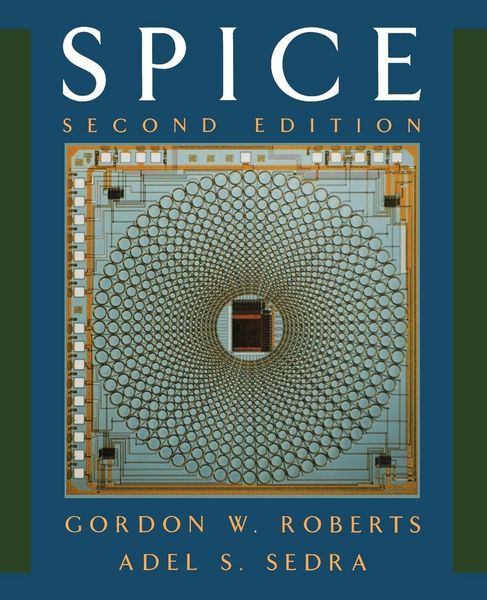
Produktbild: Spice

Spice

Fr. 179.00

inkl. gesetzl. MwSt., Versandkostenfrei


Beschreibung

Produktdetails

Einband

Taschenbuch

Erscheinungsdatum

01.09.1996

Verlag

Oxford University Press

Seitenzahl

462

Maße (L/B/H)

23.5/19.1/2.5 cm

Gewicht

794 g

Auflage

2. Auflage

Sprache

Englisch

ISBN

978-0-19-510842-2

Beschreibung

Produktdetails

Einband

Taschenbuch

Erscheinungsdatum

01.09.1996

Verlag

Oxford University Press

Seitenzahl

462

Maße (L/B/H)

23.5/19.1/2.5 cm

Gewicht

794 g

Auflage

2. Auflage

Sprache

Englisch

ISBN

978-0-19-510842-2

Herstelleradresse

Libri GmbH
Europaallee 1
36244 Bad Hersfeld
DE

Email: gpsr@libri.de

Noch keine Bewertungen vorhanden

Verfassen Sie die erste Bewertung zu diesem Artikel

Helfen Sie anderen Kundinnen und Kunden durch Ihre Meinung.

Kundinnen und Kunden meinen

Bewertungen (0)

  • Produktbild: Spice
    • Preface

    • 1: Introduction to Spice

    • 1.1: Computer Simulation of Electronic Circuits

    • 1.2: An Outline of Spice

    • 1.2.1: Types of Analysis Performed by Spice

    • 1.2.2: Input to Spice

    • 1.2.3: Output from Spice

    • 1.4: Examples

    • 1.4.1: Example 1: DC Node Voltages of a Linear Network

    • 1.4.2: Example 2: Tranient Response of a 3-Stage Linear Amplifier

    • 1.4.3: Example 3: Setting Circuit Initial Conditions During a Tranient Analysis

    • 1.4.4: Example 4: Frequency Response of a Linear Amplifier

    • 1.5: Spice Tips

    • 1.6: Bibliography

    • 1.7: Problems

    • 2: Operational Amplifiers

    • 2.1: Modeling an Ideal Op Amp with Spice

    • 2.2: Analyzing the Behavior of Ideal Op Amp Circuits

    • 2.2.1: Inverting Amplifier

    • 2.2.2: The Miller Integrator

    • 2.2.3: A Damped Miller Integrator

    • 2.2.4: The Unity-Gain Buffer

    • 2.2.5: Instrumentation Amplifier

    • 2.3: Nonideal Op Amp Performance

    • 2.3.1: Small-Signal Frequency Response of Op Amp Circuits

    • 2.3.2: Modeling the Large-Signal Behavior of Op Amps

    • 2.4: The Effects of Op Amp Large-Signal Nonidealities on Closed-Loop Behavior

    • 2.4.1: DC Transfer Characteristic of an Inverting Amplifier

    • 2.4.2: Slew-Rate Limiting

    • 2.4.3: Other Op Amp Nonidealities

    • 2.5: Spice Tips

    • 2.6: Bibliography

    • 2.7: Problems

    • 3: Diodes

    • 3.1: Describing Diodes to Spice

    • 3.1.1: Diode Element Description

    • 3.1.2: Diode Model Description

    • 3.2: Spice as a Curve Tracer

    • 3.2.1: Temperature Effects

    • 3.3: Zener Diode Modeling

    • 3.4: A Half-Wave Rectifier Circuit

    • 3.5: Limiting and Clamping Circuits

    • 3.6: Spice Tips

    • 3.7: Problems

    • 4: Bipolar Junction Transistors (BJTs)

    • 4.1: Describing BJTs to Spice

    • 4.1.1: BJT Element Description

    • 4.1.2: BJT Model Description

    • 4.1.3: Verifying NPN Transistor Circuit Operation

    • 4.2: Using Spice as a Curve Tracer

    • 4.3: Spice Analysis as a Curve Tracer

    • 4.3.1: Transistor Modes of Operation

    • 4.3.2: Computing DC Bias of a PNP Transistor Circuit

    • 4.4: BJT Transistor Amplifiers

    • 4.4.1: BJT Small-Signal Model

    • 4.4.2: Single-Stage Voltage-Amplifier Circuits

    • 4.5: DC Bias Sensitivity Analysis

    • 4.6: The Common-Emitter Amplifier

    • 4.7: Spice Tips

    • 4.8: Bibliography

    • 4.9: Problems

    • 5: Field-Effect Transistors (FETs)

    • 5.1: Describing MOSFETs to Spice

    • 5.1.1: MOSFET Element Description

    • 5.1.2: MOSFET Model Description

    • 5.1.3: An Enhancement-Mode N-Channel MOSFET Circuit

    • 5.1.4: Observing the MOSFET Current - Voltage Characteristics

    • 5.2: Spice Analysis of MOSFET Circuits at DC

    • 5.2.1: An Enhancement-Mode P-Channel MOSFET Circuit

    • 5.2.2: A Depletion-Mode P-Channel MOSFET Circuit

    • 5.2.3: A Depletion-Mode N-Channel MOSFET Circuit

    • 5.3: Descrbing JFETs to Spice

    • 5.3.1: JFET Element Description

    • 5.3.2: JFET Model Description

    • 5.3.3: An N-Channel JFET Example

    • 5.3.4: A P-Channel JFET Example

    • 5.4: FET Amplifier Circuis

    • 5.4.1: Effect of Bias Pointn on Amplifier Conditions

    • 5.4.2: Small-Signal Model of the FET

    • 5.4.3: A Basic FET Amplifier Circuit

    • 5.5: Investigating Bias Stability with Spice

    • 5.6: Integrated-Circuit MOS Amplifiers

    • 5.6.1: Enhancement-Load Amplifiers Including the Body Effect

    • 5.6.2: CMOS Amplifier

    • 5.7: MOSFET Switches

    • 5.8: Describing MESFETs to Spice

    • 5.8.1: MESFET Element Description

    • 5.8.2: MESFET Model Description

    • 5.8.3: Small-Signal MESFET Model

    • 5.8.4: A MESFET Biasing Example

    • 5.9: Spice Tips

    • 5.10: Bibliography

    • 5.11: Problems

    • 6: Differential and Multistage Amplifiers

    • 6.1: Input Excitation for the Differential Pair

    • 6.2: Small-Signal Analysis of the Differential Amplifier: Symmetric Conditions

    • 6.3: Small-Signal Analysis of the Differential Amplifier: Assymmetric Conditions

    • 6.4: Current-Souce Biasing in Integrated Circuits

    • 6.5: A BJT Multistage Amplifier Circuit

    • 6.6: Spice Tips

    • 6.7: Bibliography

    • 6.8: Problems

    • 7: Frequency Problems

    • 7.1: Investigating Transfer Function Behavior Using PSpice

    • 7.2: Modeling Dynamic Effects in Semiconductor Devices

    • 7.3: The Low-Frequency Response of the Common-Source Amplifier

    • 7.4: High-Frequency Response Comparison of the Common-Emitter and Cascode Amplfiers

    • 7.5: High-Frequency Response of the CC-CE Amplfier

    • 7.6: Spice Tips

    • 7.7: Problems

    • 8: Feedback

    • 8.1: The General Feedback Structure

    • 8.2: Determining Loop Gain with Spice

    • 8.3: Stability Analysis Using Spice

    • 8.4: Investigating the Range of Amplifier Stability

    • 8.5: The Effect of Phase Margin on Transient Response

    • 8.6: Frequency Compensation

    • 8.7: Spice Tips

    • 8.8: Bibliography

    • 8.9: Problems

    • 9: Output Stages and Power Amplifiers

    • 9.1: Emitter-Follower Output Stage

    • 9.2: Class B Output Stage

    • 9.3: Spice Tips

    • 9.4: Problems

    • 10: Analog Integrated Circuits

    • 10.1: A Detailed Analysis of the 741 Op Amp Circuit

    • 10.2: A CMOS Op Amp

    • 10.3: Spice Tips

    • 10.4: Bibliography

    • 10.5: Problems

    • 11: Filters and Tuned Amplifiers

    • 11.1: The Butterworth and Chebyshev Transfer Functions

    • 11.2: Second-Order Active Filters Based on Inductor Replacement

    • 11.3: Second-Order Active Filters Based on the Two-Integrator-Loop Technology

    • 11.4: Tuned Amplifiers

    • 11.5: Spice Tips

    • 11.6: Bibiliography

    • 11.7: Problems

    • 12: Signal Generators and Waveform - Shaping Circuits

    • 12.1: Op Amp-RC Sinusoidal Oscillators

    • 12.1.1: The Wien-Bridge Oscillator

    • 12.1.2: An Active-Filter-Tuned Oscillator

    • 12.2: Multivibrator Circuits

    • 12.3: Precision Rectifier Circuits

    • 12.4: Spice Tips

    • 12.5: Bibiliography

    • 12.6: Problems

    • 13: MOS Digital Circuits

    • 13.1: NMOS Inverter with Enhancement Load

    • 13.2: NMOS Inverter with Depletion Load

    • 13.3: The CMOS Inverter

    • 13.4: A Gallium-Arsenide Inverter Circuit

    • 13.5: Spice Tips

    • 13.6: Problems

    • 14: Bipolar Digital Circuits

    • 14.1: Transistor-Transistor Logic (TTL)

    • 14.2: Emitter-Coupled Logic (ECL)

    • 14.3: BiCMOS Digital Circuits

    • 14.4: Bibliography

    • 14.5: Problems


    • A.1: Diode Model

    • A.2: BJT Model

    • A.3: JET Model

    • A.4: MOSFET Model

    • A.5: MESFET Model

    • A.6: Bibliography


    • Index