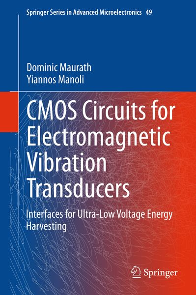
CMOS Circuits for Electromagnetic Vibration Transducers Interfaces for Ultra-Low Voltage Energy Harvesting
-
- Hardcover ausgewählt
- Taschenbuch
- eBook
-
Sprache:Englisch
Fr. 138.00
inkl. gesetzl. MwSt.,
Beschreibung
Produktdetails
Einband
Gebundene Ausgabe
Erscheinungsdatum
26.09.2014
Abbildungen
XXIII, 155 illus., schwarz-weiss Illustrationen
Verlag
Springer NetherlandSeitenzahl
300
Maße (L/B/H)
24.1/16/2.4 cm
Gewicht
653 g
Auflage
2015
Sprache
Englisch
ISBN
978-94-017-9271-4
Chip-integrated power management solutions are a must for ultra-low power systems. This enables not only the optimization of innovative sensor applications. It is also essential for integration and miniaturization of energy harvesting supply strategies of portable and autonomous monitoring systems.
The book particularly addresses interfaces for energy harvesting, which are the key element to connect micro transducers to energy storage elements. Main features of the book are:
- A comprehensive technology and application review, basics on transducer mechanics, fundamental circuit and control design, prototyping and testing, up to sensor system supply and applications.
- Novel interfacing concepts - including active rectifiers, MPPT methods for efficient tracking of DC as well as AC sources, and a fully-integrated charge pump for efficient maximum AC power tracking at sub-100µW ultra-low power levels. The chips achieve one of widest presented operational voltage range in standard CMOS technology: 0.44V to over 4.1V.
- Two special chapters on analog circuit design – it studies benefits and obstacles on implemented chip prototypes with three goals: ultra- low power, wide supply voltage range, and integration with standard technologies. Alternative design approaches are pursued using bulk-input transistor stages in forward-bias operation for amplifiers, modulators, and references.
- Comprehensive Appendix – with additional fundamental analysis, design and scaling guidelines, circuit implementation tables and dimensions, schematics, source code listings, bill of material, etc.
The discussed prototypes and given design guidelines are tested with real vibration transducer devices. The intended readership is graduate students in advanced courses, academics and lecturers, R&D engineers.Noch keine Bewertungen vorhanden
Verfassen Sie die erste Bewertung zu diesem Artikel
Helfen Sie anderen Kundinnen und Kunden durch Ihre Meinung.